Due to their variation in size and shapes, the pictures of various pieces of equipment are linked in the document.
Mining
Water
Almost all mines in Northern Ontario utilize a blasting mixture called ANFO ((A)mmonium (N)itrate - (F)uel (O)il). Holes are drilled into the ore which are then filled with the blasting mixture. A mini-explosive device called a detonator is inserted and fired to created the explosion. Ammonium nitrate is an oxidation accelerator which causes all the fuel oil to ignite almost instantaneously . The sudden pressure created by the combustion gases fractures the host rock/ore.
ANFO literally delivers the "best bang for the buck" but presents a P2 challenge in its ammonia content. Ammonium nitrate is extremely soluble in water. Mines are notoriously wet. Hence mine water tends to carry a heavy ammonia loading.
The behavior of ammonia is greatly affected by the pH of the carrying water. At pH values > 9.5, the ammonia is almost all in the NH3 form which has toxic effects in an aqueous environment. Below pH 9.5, most of the the ammonia is in the NH4 or ammonium form which is considerably less toxic.>
The sulphidic nature of most Northern Ontario ore deposits complicates the P2 challenge of mine water. Metals sulphides oxidize readily upon contact with air to form soluble sulphates which lower the pH of mine water and keep the ammonia in solution.
The standard control method uses slaked calcium oxide (lime) in a two pond system. The lime raises the mine water effluent pH to ~10.5 to ensure precipitation of dissolved heavy metals. The first pond acts as a settling chamber for the metal hydroxide precipitates. The second pond is called a "polishing pond" and is used to ensure maximal settling and stabilization of the effluent prior to discharge.
Under the Ontario Ministry of the Environment MISA regulation, mine effluents require pH adjustment down to less than 9.5 but greater than 6.0. This is usually accomplished by bubbling carbon dioxide through the final effluent or by addition of a mineral acid such as sulphuric acid.
Air
Underground mining and open pit mining have different challenges in this media.Underground mining challenges in air P2 are minor. Although huge volumes of air are injected in the mine workings to ensure adequate ventilation and heat removal, the long vertical distance of the return air vents causes them to act as settling chambers so minimal dust is emitted to atmosphere. The humid mine environment also tends to attenuate dust entrainment in return mine air.
Open pit mines are prone to fugitive dust emissions resulting from the outdoor operation of mining equipment and transport traffic. Control is usually effected by water and/or surfactant spraying.
Noise
This P2 challenge is a major factor in open pit mining. Noise berms and production scheduling are the main tools in dealing with this factor.With underground mining, intake air fans/compressors/heating and ventilation units are the main P2 challenge. This challenge is met with off-the-shelf noise abatement equipment such as silencers and mufflers
Milling
Ore from the mines is transported by truck and/or rail to the milling facility. Incoming ore, in the Sudbury area, is about 25% mineral with the rest being host rock. The processes in the mill can be split into four subprocesses; crushing, grinding, flotation, and transport/disposal.Crushing
The ore arrives from the mine in ~6 inch lumps. These are dumped from the rail car/truck into storage hoppers. From the hoppers, the lump ore is fed to a series of gyratory cone crushers. In these crushers, a hardened steel cone is eccentrically rotated within a hardened steel cylinder. The spacing between the orbit of the cone and steel wall is progressively reduced through the series of crushers to end up with a 1 to 2 inch pebble. Water is not used in this process.The P2 challenge is dust emission.
Baghouses are the control method of choice for abating these emissions. The dry material can be easily recycled.
Scrubbers are a secondary choice because of the media transfer of the P2 challenge from air to water.
While electrostatic precipitators (ESPs) are highly efficient, the dust from mills is usually non-conductive rock, which does not work well with ESP technology.
Grinding
The ore "pebbles" are then sent to grinding mills are rotating steel cylinders containng grinding media. Screens ensure a consistent product size and prevent loss of usable grinding media . Steel balls or rods are normally used as the grinding media. Recycled process water is used as both a transport and lubricating media. A high throughput type of grinding mill called a semi-autogenous grinding (SAG) milluses the feed pebbles and oversize steel balls as the own grinding media. The end product is a very fine mesh "sand".Natural environment P2 challenges are virtually non-existent in this sub-process. Dust emissions are minimal since the system is water based.
Flotation
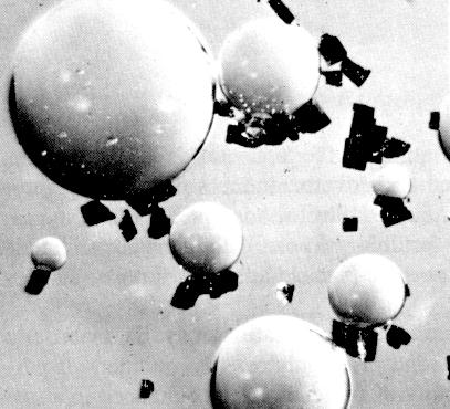 The finely ground ore slurry is fed to banks of flotation cells. Chemical(s) are added and air is blown into the bottom of the cells to create a surface layer of foam call a froth.
Various other reagents are added to different banks of cells to either enhance or reduce the adherence of specific mineral particles to the froth bubbles
The finely ground ore slurry is fed to banks of flotation cells. Chemical(s) are added and air is blown into the bottom of the cells to create a surface layer of foam call a froth.
Various other reagents are added to different banks of cells to either enhance or reduce the adherence of specific mineral particles to the froth bubblesThis effects the separation between waste rock "tailings" and the mineral species "concentrate". Separation between the mineral species can be effected by this same process using different chemicals. The froth is skimmed off and fed to magnetic separators to clean the concentrate of remaining rock.
The end products are a metal concentrate and a waste rock gangue or "tailings". Both of these can be dried on filters, such as a disc filter, or thickened for further transport as a slurry.
Natural environment P2 challenges are virtually non-existent in this sub-process.
Concentrate Transportation and Tailings Disposal
This subprocess presents the greatest P2 challenges in the Milling process. The main challenge is with waste water. The secondary challenge is dust control.
Water
The mineral concentrates are either slurried (usally with recycled mill water) or filtered and dryed for transportation to the smelting process. Slurried concentrates are thickened in a standard thickener and filtered prior to the smelting process. The filtrate is recycled back to the mill in most cases.
The waste rock fractions are slurried and pumped to a tailings impoundment. The waste solids are allowed to naturally settle. The decant water is collected and gravity flows to a waste water treatment plant (WWTP).
Upstream of the waste water treatment facility, decant water is often recycled back to the mill. The remaining decant water is treated at a WWTP to reduce the metal loadings and pH to acceptable criteria.
Water Treatment Plants
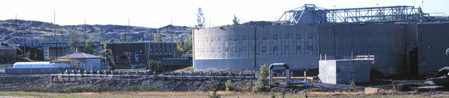
Lime and a polymer flocculant are added to the decant water as it enters a pair of parallel reactor-clarifiers. These units are modified thickeners in which the central well extends down almost to the bottom of the thickener. The pH in the reactor-clarifiers is maintained at ~10.5. The metal hydroxides formed are coagulated by the polymer into flocs. The flocs settle to the bottom of the reactor. A constant depth bed of floc is maintained in the bottom of the thickener. This floc bed acts as a filter in the system. The clarified water is drawn off through perforated pipes and discharged.
The Ontario MOE MISA regulation requires pH adjustment to below 9.5. This adjustment is most easily effected by bubbling carbon dioxide through the effluent prior to discharge. Mineral acids such sulphuric acid, which many facilities produce on-site, are also used.
Floc is extracted at a controlled rate from the bottom of the clarifiers. Since this floc material is usually uneconomic to process or would contaminate or disrupt upstream processes, most facilities pump this material to tailings areas.
Seepage Stations
Tailings impoundment dams can be designed to seep or be water tight.
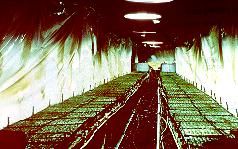
Porous dams are usually constructed of the tailings material. Rock finger drains are constructed perpindicular to the dam face at the base of the dams. These finger drains ensure that sufficient water drains out of the dam to prevent failure via liquifaction. This drainage is called seepage. Most facilities pump this seepage back up into the tailings areas. Seepage can be treated in on-site miniplants and direct discharged, but this is an unusual option.
Air
Deposited tailings are susceptible drying out and being entrained by winds. This is a year round phenomenon. During the fall and winter, a freeze-dry effect takes place in the upper layers of the deposited tailings. Winds in excess of 7 ms-1 will result in dust storms.

Revegetation of tailings area is the preferred method of handling this P2 challenge, but is limited to non-active areas. For active areas, straw mulching creates a stable surface layer. For sloped areas, a surfactant is sprayed onto the exposed areas. The surfactant forms a hard coating thereby preventing wind erosion. One of the promising surfactants is waste lignin from the Pulp and Paper Industry. This uses a P2 challenge from that industry to handle a P2 challenge in our industry.
Once tailings areas are full, they can be reclaimed by standard agriculatural techniques. For Sudbury area tailings, lime, fertilizer, and a specially developed seed mix are spread over the surface. Once ground cover is established, coniferous trees (some of which are grown underground locally) are planted. Deciduous trees naturally take root.

After several years, the once barrent tailings support a thriving ecosystem.
Noise
Most mills tend to be located away from populated areas. The grinding process produces most of the noise in Milling. Noise tends to be a workroom issue rather than a natural environment issue.Smelting
The P2 challenges from this process are heavy metal dusts, slag, and sulphur dioxide for sulphide ore processors
Drying
Some furnaces require a dry concentrate.
Fluid-bed dryers are often used for this purpose. Hot air or combustion gases are injected via "tuyeres" in the bed of the unit through the a fixed thickness of concentrate. A fluidized bed, resembling a boiling pot of soup, is created. Dried concentrate elutes with the offgas. Feed addition rates are adjusted to maintain bed depth and prevent the whole bed from eluting. Dust removal devices such as baghouses are used to remove the dried concentrate from the offgas stream for processing
Various type of external steam or electric dryers are also used
The concentrate feed storage and transfer systems have recycling dust control baghouses to minimize metal loss and reduce workroom contamination.
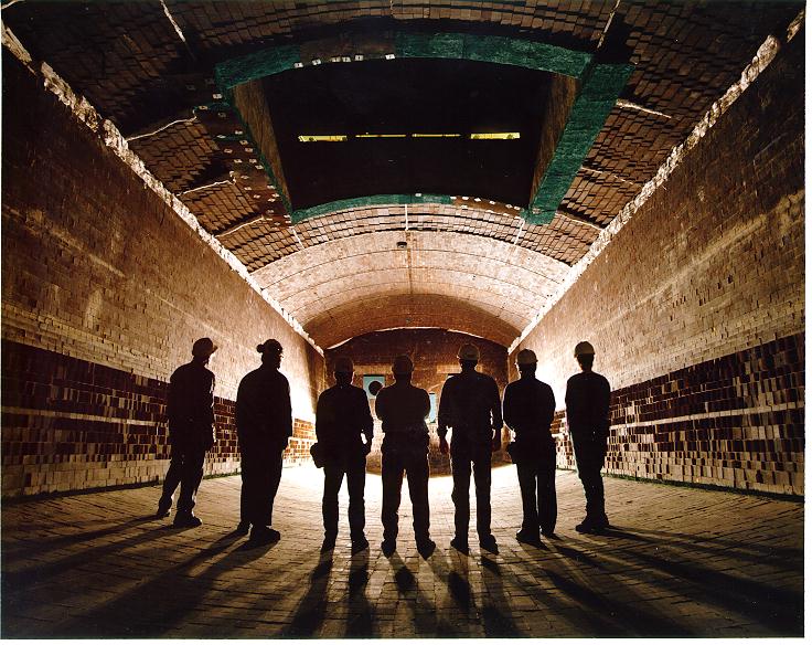
Furnaces
The concentrate is fed to furnaces which may or may not require fossil fuel addition. Dependant on furnace type, pure oxygen, oxygen enriched air or ambient air are used for combustion purposes. In most furnaces, some sort of flux such as sand is also added to combine with the iron content of the concentrate as an iron silicate "slag". A large portion of the sulphur content is driven off as sulphur dioxide.
The older technology furnaces {blast,multiple hearth, reverberatory, electric} produce low strength sulpur dioxide gases unsuitable for further processing. They also require the combustion of a large amount of fossil fuel for heat. Large volumes of acid-generating greenhouse gases are routed to atmosphere out of economic necessity.
The offgases carry significant amounts of fine entrained heavy metal dust which must be routed to dust control units prior to discharge.
Fluid bed roasters are used as refining furnaces. If feed sulphur concentration is high enough, offgases at 10 to 12% sulphur dioxide can be generated. This offgas is ideal feedstock for most of the the world's sulphuric acid plants.
Flash Furnaces
Flash smelting furnaces are being installed globally to replace these older furnaces mainly due to the fact they are autogenous with respect to smelting and produce offgases at 50-75% sulphur dioxide.
Oxidation of sulphur to sulphur dioxide generates heat. In flash furnaces, this reaction provides the smelting process heat requirements; hence the label autogenous. Minor amounts of fossil fuel may be required dependant on feed sulphur content. Use of flash furnace technology can eliminate or, at minimum, greatly reduce the P2 challenge of greenhouse gases.
Flash furnace offgases are often diluted to serve as feedstock to a sulphuric acid plant or can be compressed generating liquid sulphur dioxide. The offgas contains fine particulate which be removed prior to fixation. A media transfer of heavy metal dusts entrained in the furnace offgases occurs from air to water. A multi-stage cleaning process is used including a quencher, reverse jet scrubbers,gas scrubbers,froth column, and wet ESP.
The acidic underflow from the cleaning process is treated with lime for pH adjustment. The high value solids are filtered out and recycled back as furnace feed. The water is recycled back to the cleaning process.
The iron silicate slag is in vitreous form. As such, it resists weathering and leaching. The molten slag is skimmed off the furnace and transported via open specialized rail cars or vehicles to onsite dumps.
Converters
The high metal/metal sulphide concentration furnace "matte" is transferred to converters for finishing into Bessemer matte. In the non-ferrous metal (NFM) industry, iron is the material most often being removed in this process. Flux is added to generate iron silicate slag. This slag is almost always recycled back to the furnaces because of the high levels of entrained matte. The offgases from these units contains ~1% sulphur dioxide and heavy metal particulates creating the same P2 challenges as the furnaces.
The offgases are usually routed to ESPs for dust removal prior to venting to atmosphere. The dust from the ESPs throughout the smelting process are recycled back as furnace feed. Scrubbers are not an option for most NFM industries as the dust is highly sulphated and therefore very soluble in water, acids, and alkalis.
"Fugitive" emissions occur during ladle movement and pouring into and out of the converters. 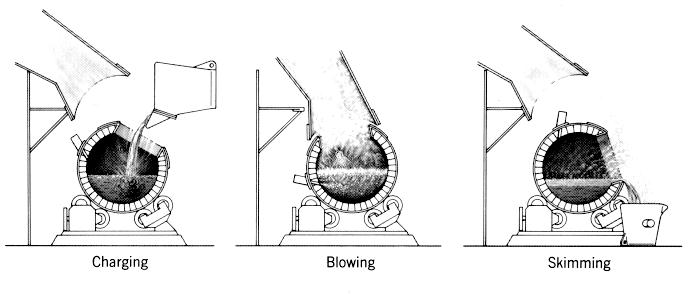
These emissions contain sulphur dioxide and particulates which are discharged at roof level.
Sulphur Dioxide and Media Transfer
The prime P2 challenge in smelters is sulphur dioxide. The older furnace technologies of reverberatory and multi-hearth furnaces produced offgases at 1 to 2% by volume sulphur dioxide. There is no process other than scrubbing which can be used to treat these weak offgases.
The flash furnace technology produces offgases containing between 50 and 75% sulphur dioxide. This gas is highly suitable to direct compression to make liquid sulphur dioxide or for dilution down to the 10 to 12% ideal sulphur dioxide content for sulphuric acid plants.
Conversion of sulphur dioxide to elemental sulphur is not a viable option for pyrometallurgical facilities. Enormous quantities of fossil fuel are required to effect the conversion. This results in the release of additional acid-generating greenhouse gas. It is also counter productive as the main use of elemental sulphur is to make sulphur dioxide for feed to acid plants.
Hydrometallurgical techniques are proven for treatment of metal sulphides. There is the issue of media transfer. Large quantities of waste calcium sulphate (gypsum) are produced. Due to the poor quality of the gypsum precipitate, landfilling is the only viable disposal option. Reclamation of this area would be very complex. This same issue is applicable to scrubbing of cleaned furnace offgases.
Noise
Noise is normally not an issue in smelting process.
Created by Dan Bouillon 981025
Revised 010721
The older technology furnaces {blast,multiple hearth, reverberatory, electric} produce low strength sulpur dioxide gases unsuitable for further processing. They also require the combustion of a large amount of fossil fuel for heat. Large volumes of acid-generating greenhouse gases are routed to atmosphere out of economic necessity.
The offgases carry significant amounts of fine entrained heavy metal dust which must be routed to dust control units prior to discharge.
Fluid bed roasters are used as refining furnaces. If feed sulphur concentration is high enough, offgases at 10 to 12% sulphur dioxide can be generated. This offgas is ideal feedstock for most of the the world's sulphuric acid plants.
Flash Furnaces
Flash smelting furnaces are being installed globally to replace these older furnaces mainly due to the fact they are autogenous with respect to smelting and produce offgases at 50-75% sulphur dioxide.
Oxidation of sulphur to sulphur dioxide generates heat. In flash furnaces, this reaction provides the smelting process heat requirements; hence the label autogenous. Minor amounts of fossil fuel may be required dependant on feed sulphur content. Use of flash furnace technology can eliminate or, at minimum, greatly reduce the P2 challenge of greenhouse gases.
Flash furnace offgases are often diluted to serve as feedstock to a sulphuric acid plant or can be compressed generating liquid sulphur dioxide. The offgas contains fine particulate which be removed prior to fixation. A media transfer of heavy metal dusts entrained in the furnace offgases occurs from air to water. A multi-stage cleaning process is used including a quencher, reverse jet scrubbers,gas scrubbers,froth column, and wet ESP.
The acidic underflow from the cleaning process is treated with lime for pH adjustment. The high value solids are filtered out and recycled back as furnace feed. The water is recycled back to the cleaning process.
The iron silicate slag is in vitreous form. As such, it resists weathering and leaching. The molten slag is skimmed off the furnace and transported via open specialized rail cars or vehicles to onsite dumps.
Converters
The high metal/metal sulphide concentration furnace "matte" is transferred to converters for finishing into Bessemer matte. In the non-ferrous metal (NFM) industry, iron is the material most often being removed in this process. Flux is added to generate iron silicate slag. This slag is almost always recycled back to the furnaces because of the high levels of entrained matte. The offgases from these units contains ~1% sulphur dioxide and heavy metal particulates creating the same P2 challenges as the furnaces.
The offgases are usually routed to ESPs for dust removal prior to venting to atmosphere. The dust from the ESPs throughout the smelting process are recycled back as furnace feed. Scrubbers are not an option for most NFM industries as the dust is highly sulphated and therefore very soluble in water, acids, and alkalis.
"Fugitive" emissions occur during ladle movement and pouring into and out of the converters.
These emissions contain sulphur dioxide and particulates which are discharged at roof level.
Sulphur Dioxide and Media Transfer
The prime P2 challenge in smelters is sulphur dioxide. The older furnace technologies of reverberatory and multi-hearth furnaces produced offgases at 1 to 2% by volume sulphur dioxide. There is no process other than scrubbing which can be used to treat these weak offgases.
The flash furnace technology produces offgases containing between 50 and 75% sulphur dioxide. This gas is highly suitable to direct compression to make liquid sulphur dioxide or for dilution down to the 10 to 12% ideal sulphur dioxide content for sulphuric acid plants.
Conversion of sulphur dioxide to elemental sulphur is not a viable option for pyrometallurgical facilities. Enormous quantities of fossil fuel are required to effect the conversion. This results in the release of additional acid-generating greenhouse gas. It is also counter productive as the main use of elemental sulphur is to make sulphur dioxide for feed to acid plants.
Hydrometallurgical techniques are proven for treatment of metal sulphides. There is the issue of media transfer. Large quantities of waste calcium sulphate (gypsum) are produced. Due to the poor quality of the gypsum precipitate, landfilling is the only viable disposal option. Reclamation of this area would be very complex. This same issue is applicable to scrubbing of cleaned furnace offgases.
Noise
Noise is normally not an issue in smelting process.
Created by Dan Bouillon 981025
Revised 010721
The flash furnace technology produces offgases containing between 50 and 75% sulphur dioxide. This gas is highly suitable to direct compression to make liquid sulphur dioxide or for dilution down to the 10 to 12% ideal sulphur dioxide content for sulphuric acid plants.
Conversion of sulphur dioxide to elemental sulphur is not a viable option for pyrometallurgical facilities. Enormous quantities of fossil fuel are required to effect the conversion. This results in the release of additional acid-generating greenhouse gas. It is also counter productive as the main use of elemental sulphur is to make sulphur dioxide for feed to acid plants.
Hydrometallurgical techniques are proven for treatment of metal sulphides. There is the issue of media transfer. Large quantities of waste calcium sulphate (gypsum) are produced. Due to the poor quality of the gypsum precipitate, landfilling is the only viable disposal option. Reclamation of this area would be very complex. This same issue is applicable to scrubbing of cleaned furnace offgases.
Noise
Noise is normally not an issue in smelting process.Created by Dan Bouillon 981025
Revised 010721